Prepare the SVG file for CNC cut
The tutorial how to convert a drawing in SVG to G-code for CNC cut with a veiseliha.com converter.
Contents
![]() Shape description in vector graphic editors
Shape description in vector graphic editors
![]() Fill - milling a pocket/cavity
Fill - milling a pocket/cavity
![]() Zigzag - milling a pocket/cavity, zigzag only
Zigzag - milling a pocket/cavity, zigzag only
![]() Oultine - milling the shape inner outline
Oultine - milling the shape inner outline
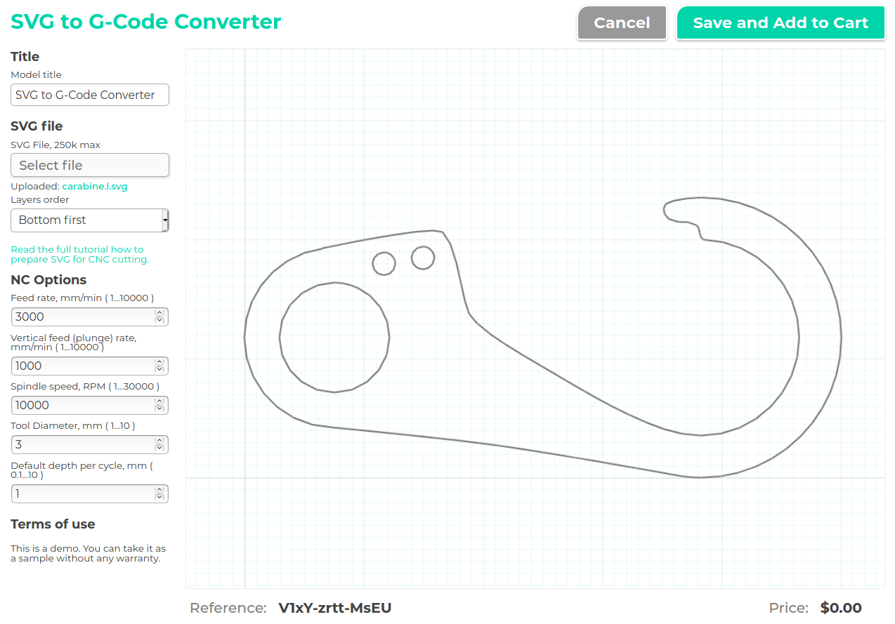
The samples

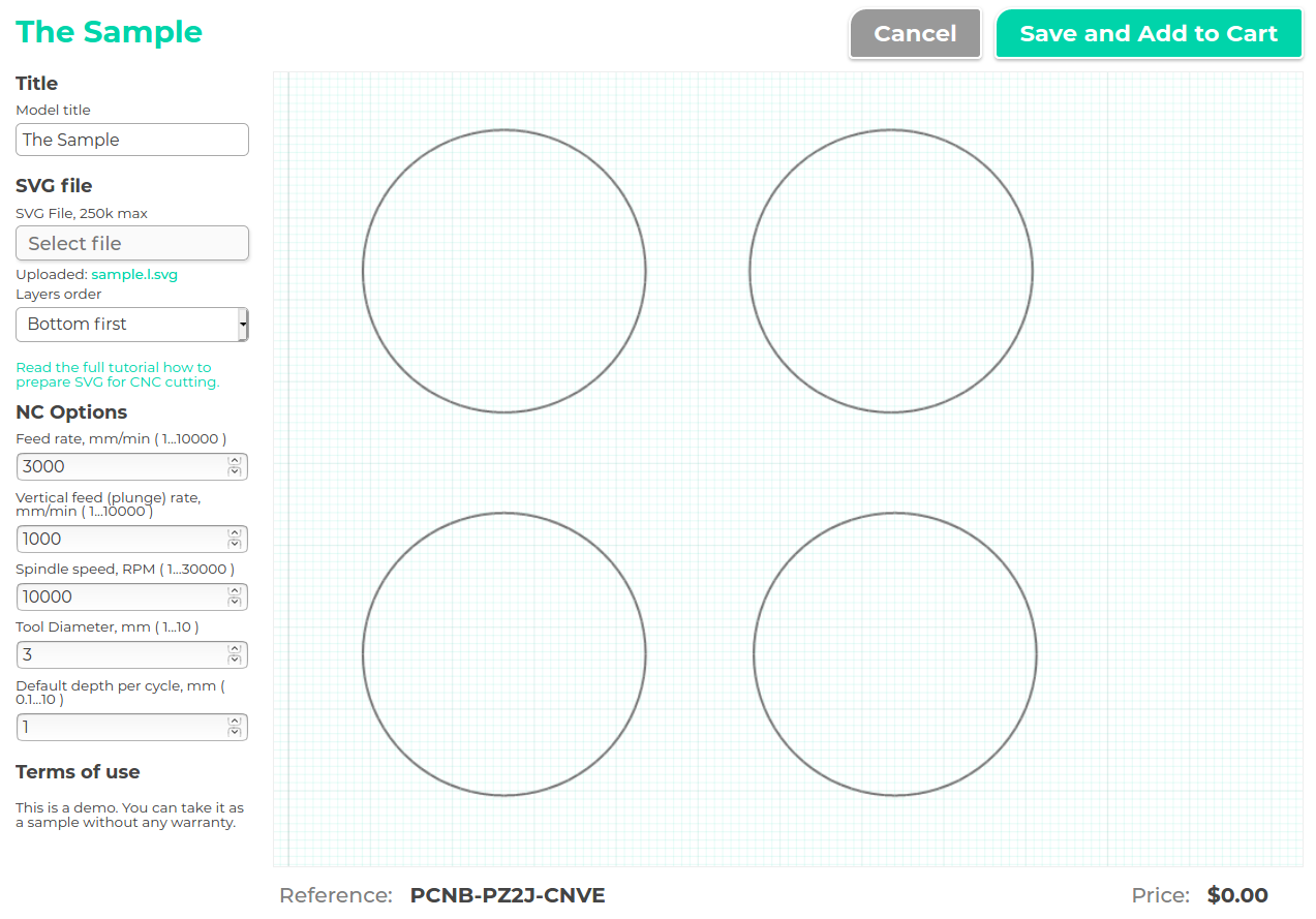

Common rules
The all shapes you want to cut should be path elements and have a special description which says converter count it as the shape for CNC cutting. You can keep any other shapes you want in the SVG file without description and they will be ignored.
For example, you may want to keep all steps of creating your model. Just place it aside the final drawing to use them when you need.
The shapes should be positioned without transforms. Some SVG editors like Inkscape love transforms but converter doesn't support them. So apply all transforms or don't use them to convert it correctly.
Pay attention to the layers order. By default, processing goes from the bottom layer to the top. It can be reversed in the editor.
Break complex shapes into some simple. The converter tries to be smart and know what shape is inside an other, but it may be wrong on too complex shapes. And the demo version is less smart as it is an older version. The calculation time for one SVG file is limited in the demo version, so too complex shapes will fail it.
We recommend to name the SVG file like name.l.svg to differ the ready to convert SVG file from usual SVG file.
Shape descriptions
Description of the shape you want to cut may begin from one of keywords:
![]() blank - scaling the other shapes
blank - scaling the other shapes
![]() cut - cutting the shape by outline
cut - cutting the shape by outline
![]() fill - milling the shape as pocket/cavity, both zigzag and inner outline
fill - milling the shape as pocket/cavity, both zigzag and inner outline
![]() zigzag - milling the shape as pocket/cavity, zigzag only
zigzag - milling the shape as pocket/cavity, zigzag only
![]() outline - milling the inner outline of the shape
outline - milling the inner outline of the shape
Shape description in vector graphic editors
How to set path description in editor? The example is Inkscape.
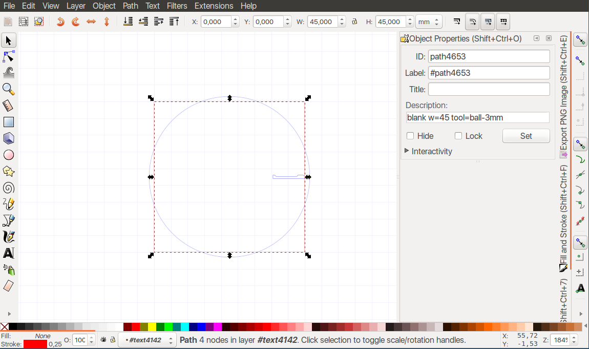
Click with the right mouse button on the path you want, select "Object Properties..." menu item and fill the field "Description:" in the Object Properties panel.
Blank - scaling shapes
The path that defines scaling of other shapes. Usually a rectangle converted to path.
blank w=100
This means that all shapes will be scaled relatively to blank shape and the X, Y zero will be at bottom left of this shape. The parameters:
![]() w, h - width, height of blank
w, h - width, height of blank
In most cases you need only one of them. Use both if you want to flatten the result.
Cut - cutting by the outline

Cutting the shape. Cutting with default Z step:
cut z=0...-10 part-name
Custom Z step:
cut z=0...-10 dz=2 part-name
Gradient Z step:
cut z=0...-10 dz=2...3...1 part-name
Single outline
cut z=0...-10 dz=2...3...1 outline=single part-name
The parameters:
![]() z - cuttind depth, from...to
z - cuttind depth, from...to
![]() dz - cutting Z step
dz - cutting Z step
![]() outline - may be single or double, by default it's double to make cutting easier
outline - may be single or double, by default it's double to make cutting easier
![]() part-name - keyword of current part to make it more clear what part is processing
part-name - keyword of current part to make it more clear what part is processing
Fill - milling a pocket/cavity

Milling the shape as a pocket/cavity. Milling with default Z step:
fill z=0...-10 part-name
Custom Z step:
fill z=0...-10 dz=2 part-name
Gradient Z step:
fill z=0...-10 dz=2...3...1 part-name
The parameters:
![]() z - milling depth, from...to
z - milling depth, from...to
![]() dz - milling Z step
dz - milling Z step
![]() part-name - keyword of current part to make it more clear what part is processing
part-name - keyword of current part to make it more clear what part is processing
Zigzag - milling a pocket/cavity, zigzag only

All like in Fill but without inner outline.
zigzag z=0...-10 dz=2...3...1 part-name
Oultine - milling the shape inner outline

All like in Fill but without zigzag.
outline z=0...-10 dz=2...3...1 part-name
Troubleshooting
Layer is not cutting - make sure the description belongs to path, not group. Make sure the shape you want to cut is a path.
The part has wrong position or size - make sure the path has no transform, transforms are not supported.
All parts are the same size and it's wrong - make sure the blank shape is created and it is a path.
Demo version limitations
![]() The main limitation is using an older version of converter. This means less optimizations and more unfixed issues.
The main limitation is using an older version of converter. This means less optimizations and more unfixed issues.
![]() Curve interpolation accuracy is less than in commercial version.
Curve interpolation accuracy is less than in commercial version.
![]() The tool size, Z step, and some other options may have limits.
The tool size, Z step, and some other options may have limits.
![]() Calculation time is limited so break complex models into some simple.
Calculation time is limited so break complex models into some simple.
![]() No any warrany.
No any warrany.
Commercial version features
![]() The newer app version, more tool path optimizations and more stable result.
The newer app version, more tool path optimizations and more stable result.
![]() Draw keyword - milling a path exactly by the line.
Draw keyword - milling a path exactly by the line.
![]() Profile and Set-profile keywords - milling a profiled edge with ball or flat end-mill tool.
Profile and Set-profile keywords - milling a profiled edge with ball or flat end-mill tool.
![]() The ability to have a set of tools and select the tool in the blank description.
The ability to have a set of tools and select the tool in the blank description.
![]() Using the app as the external API in automated process or with a web UI.
Using the app as the external API in automated process or with a web UI.
![]() The extended support.
The extended support.